
Making a pure sine wave inverter is very easy using the EGS002, especially for low-frequency transformer-type inverters.
All we need are some external components to make the H-Bridge driver and the step-up transformer. Test the newly purchased EGS002 module first before installing it on the H-Bridge circuit, see the post about the EGS002 functional test.
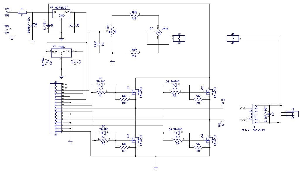
Inverter Schematic
Using an inverter circuit taken from the EG8010 datasheet with a few changes. Currently, the IFB and TFB inputs will not be used, so these two inputs are grounded. Add a 5V regulator circuit in addition to 12V. The overcurrent sensor (IFB) is disabled then add a fuse to handle overcurrent protection.
Inverter PCB
PCB layout is made single layer to make it easier when making it. PCB path is wide enough, especially for paths through which large currents pass. That is, the path connected to the drain and source of the MOSFET. Other paths such as the path for voltage feedback and the SPWM signal path to the MOSFET gate do not need to be wide.
Install all the necessary components on the PCB, there are not many components to assemble so making the inverter can be done quickly and easily.
Unfortunately, the EG8010 datasheet does not provide an explanation of the transformer used. So as an experimental material, I used a used 600VA UPS transformer to try it, when measured this transformer outputs 6.7V AC at the 220V AC input. The estimated power of the transformer is only 100 watts


Test Run
Because only about 100 watts of power will be tested according to the capacity of the transformer, a 12V 25A power supply is used. The load uses a resistive load, in the form of a parallel incandescent lamp.
How this test is done, please see the test video via the link below.
Result
Following are the results of the tests that have been carried out.
No Name Value 1 Voltage output 220V AC ± 6% 2 Total Harmonic Distortion (THD) 2.75% 3 Frequency 50 Hz ± 0.05 4 Efficiency 70%
So far I am quite satisfied with the results. Just a little disappointed with the efficiency results,
although maybe this is because the transformer used is not suitable.
How about you, interested?