
Table of contents
- Introduction
- Simplifying the Arduino Nano SPWM Card
- Incorporating Over-Current Protection
- Improvements to the code
- Conclusion
1. Introduction
In this ATmega328P PWM card project, I want to simplify the Arduino Nano SPWM card, or Arduino Nano SPWM with TLP250 which is a project I have previously created.
2. Simplifying the Arduino Nano SPWM Card
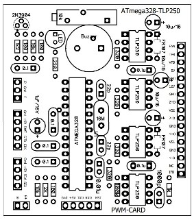
The simplification I am doing is by directly using the ATmega328P microcontroller on the SPWM card without using the Arduino Nano development board. Therefore, I do not use the supporting circuitry found on the Arduino Nano here.
The ATmega328P I am using is the microcontroller installed on the Arduino Uno, in other words, using the ATmega328P with the Bootstrap Loader. This allows me to reprogram it with the Arduino IDE as usual, so this card functions similarly to a development board for PWM generation. I added a 5-pin header to the circuit to accommodate programming needs.
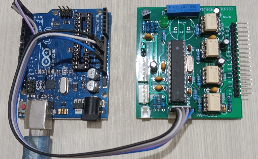
I perform the program upload using the Arduino Uno board without the ATmega328P IC inside to avoid interfering with the program uploading process.
3. Incorporating Over-Current Protection
There is a newly added function that was not present in the previous version of the Arduino Nano SPWM card, namely the addition of Over-Current Protection. With this added function, it is expected that this ATmega328P PWM Card can be an alternative to the EGS002 module while having flexibility for further development.
The addition of the new function results in additions or changes to the hardware, in addition to the software, of course.
3.1. ATmega328P PWM card Hardware
The EGS002 module uses an Op-Amp as an interface to detect Over-Current events, and the same goes for this card. I use the On-Chip Analog Comparator available on the ATmega328P, making the circuitry simpler. Therefore, it is only necessary to activate the On-Chip Analog Comparator in the code.
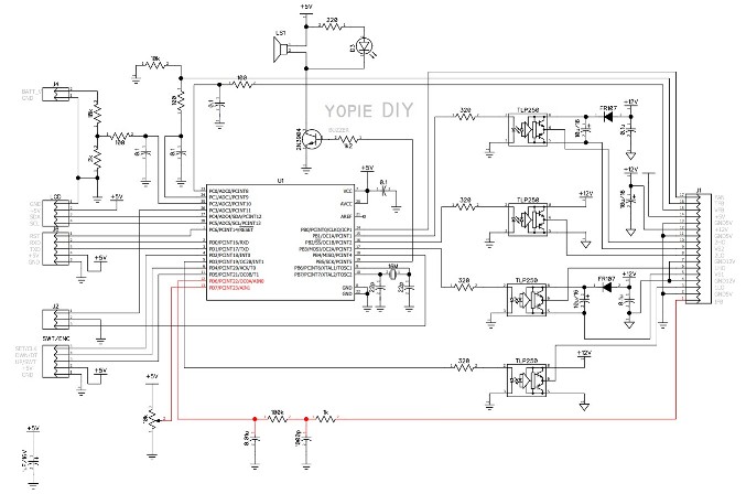
In the circuit diagram above, the red-coloured line represents the new path for the Over-Current detection function through the IFB pin. This circuit is connected from the IFB pin to the AIN0 pin after passing through an RC filter. Additionally, the AIN1 pin is connected to a 10 kOhm trim potentiometer, which serves as the voltage reference for the analog comparator.
The Over-Current detection on the IFB pin only works in circuits with Full-Bridge MOSFETs that have a shunt resistor circuit. The voltage across this shunt resistor will trigger the Over-Current alarm. For example, if I use a 0.1 Ohm shunt resistor, when there is a current greater than 5 Amps, the warning indication will be triggered.
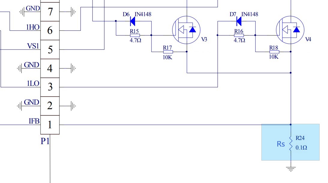
The picture above with a blue background is a shunt resistor
3.2. ATmega328P PWM card Software
The coding additions for this function include the library declaration, ISR initialization, ISR function writing, and additions to the warning indication function, as follows:
First, I add the library for the On-Chip Analog Comparator.
#include <analogComp.h>Next, initialize the port for the On-Chip Analog Comparator.
pinMode(AIN0, INPUT);
pinMode(AIN1, INPUT);
Then, initialize the On-Chip Analog Comparator. Here, the analogComparator is connected to the AIN0 and AIN1 ports, and the interrupt service routine is activated. The ISR named interruptOverCurrent will be executed when the output of the analogComparator changes from LOW to HIGH (RISING).
analogComparator.setOn(AIN0, AIN1);
analogComparator.enableInterrupt(interruptOverCurrent,RISING);
The output of the analogComparator changes to HIGH when the voltage condition at AIN0 (IFB pin) is greater than the reference voltage set at AIN1. In the case of EGS002, this voltage value is set at 0.5V, and I follow the same value for this card as well.
To adjust to this voltage, I set my trim potentiometer to 1kOhm between the wiper pin and ground. This setting provides a value of 0.5V at the AIN1 pin. When the voltage at AIN0 (IFB) exceeds 0.5V, the On-Chip Comparator changes its level from LOW to HIGH.
This event triggers the ISR function interruptOverCurrent, which is responsible for disabling the PWM output and activating the alarmOC flag.
void interruptOverCurrent() {
    TCCR1A = 0;
    alarmOC = 1;
}
In the loop, when the alarmOC flag equals 1, the alarmIndication routine is executed. This causes the LED to blink and displays the Over-Current warning.
if (alarmOC==1 && digitalRead(J2)==HIGH) alarmIndication(7);4. Improvements to the code
4.1. Removing the power On button
In the ATmega328P PWM card project, I have removed the Power On function due to my consideration that this function is less useful and can impact safety. In this case, when the inverter is off, power is still available in the circuit, while I want the power to be completely disconnected from its source. The best way to achieve this is by physically disconnecting all connections, for example, using a switch or a contactor.
4.2. Look-Up Table generator
To make it easier to change the output frequency, I have made modifications to the relevant part. First, let’s consider the Look Up Table (LUT). Previously I calculated the LUT using a spreadsheet, and then I entered the results as entries in the LUT. When changing the frequency, this process had to be repeated, which was quite cumbersome.
//---------------------------------Look Up Table for 50 Hz---------------------------------------
int lookUp1[] = {
  0,25, 50, 75, 100, 125, 150, 175, 199, 223, 247, 271, 294, 318, 341, 363, 385, 407, 429, 450,
  470, 490, 510, 529, 548, 566, 583, 600, 616, 632, 647, 662, 675, 689, 701, 713, 724, 734, 744, 753,
  761, 768, 775, 781, 786, 790, 794, 796, 798, 800, 800, 800, 798, 796, 794, 790, 786, 781, 775, 768,
  761, 753, 744, 734, 724, 713, 701, 689, 675, 662, 647, 632, 616, 600, 583, 566, 548, 529, 510, 490,
  470, 450, 429, 407, 385, 363, 341, 318, 294, 271, 247, 223, 199, 175, 150, 125, 100, 75, 50, 25, 0
};
And now I have added a calculation function related to the Look Up Table (LUT). By simply changing the desired frequency value, the LUT and other parameters related to SPWM generation will adjust accordingly. The formula for the calculation I used is the same as the one I used in the spreadsheet, but here I have incorporated the formula directly into the code.
int LUT[samples];

void initLUT() {
  int sineVal;
  for (int i=0; i<samples; i++){
    int sineVal = int(sin(radians(deg*i))*icr + 0.5);
    LUT[i] = sineVal;
  }
}
The contents of the Look Up Table (LUT[i]) generated by this function are exactly the same as the values in lookUp1[i] mentioned earlier. For example, if the value of lookUp1 is 25, the value assigned to LUT[1] will also be 25.
By running this function, the frequency output can be easily changed by modifying the value of the constant fMod. For a frequency of 60 Hz, the values are as follows:
const int fMod = 60,4.3. Improving Code Readability
In addition, there are adjustments in the coding structure in the setup() function. In the previous version, all initializations were combined into one setup() function, which made it difficult to evaluate specific parts of the initialization if needed. To simplify it, I have divided it into several functions, one function for each specific task group.
void setup() {
  initLUT();
  initTimer();
  initPort();
  initAnalogComp();
  welcomeScreen();
  softStart();
  uploadEEPROM();
  alarmOC=0;
  Serial.begin(115200);
  lcd.clear();
  lcd.setCursor(0, 0);
  lcd.print("Batt--Vout--Temp");
}
With the exception of the initLUT() function, the other functions represent specific task groups from previous versions of the code. For example, all pinMode commands are now collected in the initPort() function.
Regarding the hardware, there are some changes in the I/O lines used here compared to the I/O ports in the Arduino Nano version. Thus, the port initialization also undergoes changes.
5. Conclusion of ATmega328P PWM Card
In conclusion, the project simplified the Arduino Nano SPWM card by directly using the ATmega328P microcontroller without the Arduino Nano board. The addition of Over Current Protection and improvements in frequency adjustment and coding structure enhance the functionality and usability of the ATmega328P PWM card.